In this short tutorial series, we will explore the ESP-Rainmaker framework by Espressif. In our first tutorial we see what the ESP-Rainmaker is and how it can help you develop your IoT application.
Introduction #
All IoT projects have a thing part in common: connectivity. Sure, applications may widely differ (logging, lighting, motor control – the list is endless) but in the end, your IoT node has to communicate the collected data to the user and has to receive commands back. All of this is done using standard procedures and protocols, usually MQTT and HTTP. This could be easy enough, but nowadays you need to ensure that your data is securely stored and collected hence you have to deal with certificates and with secure and privacy-focused provisioning.
Every IoT project can be divided in two parts: the application and the connectivity. It’s important to focus on the former, which is the part which makes the project interesting and to deal with the second as fast as possible. This is even more important when the developer is trying their first IoT project and doesn’t have any prior experience with wireless connectivity. The last thing they want is to get lost in the security details of the connectivity.
Espressif developed ESP-Rainmaker specifically to speed up and simplify the connectivity development, thus considerably reducing the development time.
In the next section, we’ll look at an overview of a typical IoT application, detailing its moving parts in both the initial setup (provisioning) and normal operation. We’ll then describe the ESP-Rainmaker in its three components, namely the IoT Node, the server and the smartphone app.
Overview of a typical IoT Application #
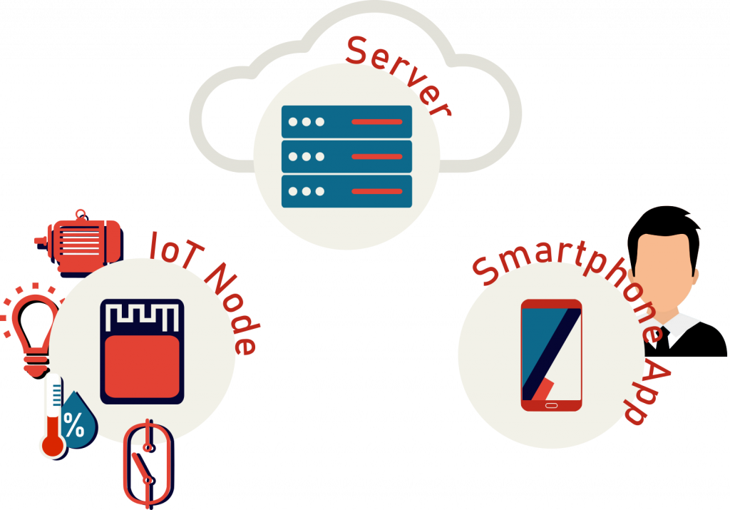
A modern IoT application has three main components:
- The device a.k.a. the IoT node – for our purposes an ESP32-* family module
- The Server service, i.e. the backend usually hosted in the cloud.
- The user interface, today almost invariably a smartphone app
Let’s take a closer look on how these three elements interact during the system setup and the following normal operation.
System setup and provisioning #
There are two main steps which must be taken before using an IoT node: the provisioning and the user/nodes registration. The first step is mandatory and it consists in sending the router credentials (SSID and password) to the IoT node. This must be done by the end user and it means that a suitable and easy-to-use user interface is required – and it’s not a trivial task to develop it.
The second step is to register in the backend server both the user and the node, which must be associated with the user themself. To do so, the user must sign up in the cloud server and must receive a unique identifier which all the devices they register are linked to. This ensures that all the devices which are registered can be controlled and monitored only by the user themself.
As a developer, this usually means developing an HTTP REST API with end points to register the user (possibly supporting OAuth2 thus allowing third party sign in options), let them manage their password and register nodes etc.. All of this must be done securely, by means of server side certificates and access tokens.
Normal Operation Workflow #
The application specific part of an IoT node is the motor driving, relays activating or sensor reading and the node must communicate any data and receive input from the user. To do so, usually the MQTT(s) protocol is used.
The IoT node acts as an MQTT client while the cloud runs the MQTT server, called an MQTT broker. On the other hand, the user reads and inputs commands on the smartphone app, which also acts as an MQTT client, connected to the same broker thus communicating with the IoT node.
To be more precise, since the MQTT is a "publish and subscribe" protocol, we should say that the IoT node subscribes to a channel on which it publish its data and listens to the command published by the smartphone app.
In addition to the collected data, the IoT node can also send its configuration, informing the smartphone app about its functionalities and the node parameters which can be controlled and read.
Nodes and devices #
Before moving to the ESP-Rainmaker detail, let’s give two definitions: node and device.
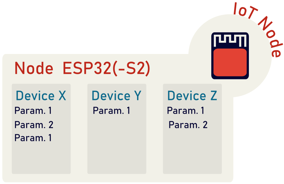
In the ESP-Rainmaker framework, the node is the physical device, i.e. the ESP32 or ESP32-S2 based module on which the firmware runs, while the device is the single function performed (or the "logical entity", as described by the official documentation). Examples of devices are switches, lightbulbs or fans. A single node can have multiple devices, as shown in the picture above.
In turn each device has several parameters, among which is the name, which is a string and is always present. Two examples of parameters are:
- power: a boolean which indicates the device state (on or off)
- brightness: a float which represents the light intensity of a light bulb
ESP-Rainmaker #
ESP-Rainmaker is a framework which takes care of everything between the application firmware and the user interface. In the image below, you can find the main parts which constitute the ESP-Rainmaker:
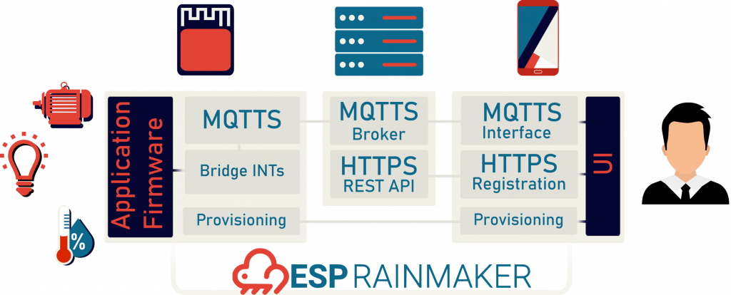
It has three parts:
- ESP-IDF libraries
- The Cloud (both MQTT broker and HTTPs REST API for user registration)
- A Smartphone app
Let’s take a look into each of them separately.
ESP-IDF Libraries #
To simplify the application’s interface to the web, ESP-Rainmaker lets you easily define the devices in the firmware. You can either define a custom device by explicitly listing the parameters or you can use a standard device type.
Below is a list of standard devices, such as switch, temperature sensor, fan and lightbulb, which can be instantiated more easily and will be voice controlled through Alexa.
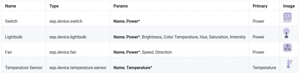
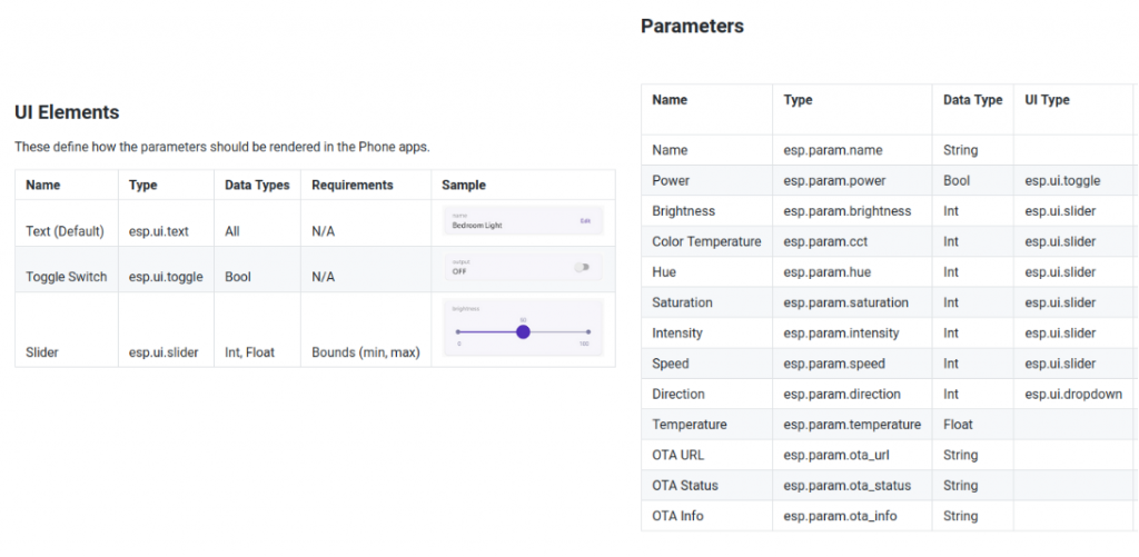
When you define your device type and parameters, the smartphone app retrieves the configuration from the IoT node and knows exactly which kind of UI element to show to the user. For instance, in the case of a switch, a toggle is shown. In the picture above you can find the table with all the supported UI elements and device parameter so far.
The other thing you specify when instantiating a device type is the callback function. When the user acts on the app UI element by toggling a switch or by choosing a brightness value, the callback function associated with it is called and the input value(s) are passed to it. This way the firmware designer can focus on the callback function and leave the rest to be handled by the framework itself.
The Cloud #
The cloud is completely transparent for the ESP-Rainmaker user and takes care of the user sign up process and management, the registration of the nodes and the association of the nodes with the user (REST API). Moreover it acts as a bridge between the smartphone app and the device on the field (MQTT).
A Smartphone app #
The smartphone app is the user interface. Through the app the user can provision, register and control the devices. You can test the app by downloading it from the Play Store or the App Store. Both versions of the software are also available on github: (Android and iOS). It’s open source and under Apache License, which is also suitable for commercial uses.
This app is really useful to prepare proof of concept (PoC) and to rapidly design your application.
Conclusion #
With the ESP-Rainmaker you can set up a proof of concept for an IoT application in a few hours. You only need to instantiate the device types you want on your IoT node and write the callback functions. No Java, Object-C for the app or PHP, Ruby, Node.js for the backend development is required.
In the next tutorial, we’ll see how to develop a simple smart plug.


