
Introduction #
This tutorial assumes that you’ve gone through the tutorial Getting Started with NuMaker-M032KI (pt 1) before. We will use some basics learned there in this tutorial without explaining it in detail again.
In this tutorial we will set up a project from scratch, letting the user LED on the NuMaker-M032KI blink about every one second. We will use Keil µVision 5 IDE and parts of CMSIS-Core for doing this.
Step 1: Open µVision 5 IDE and create a new Project #
Create Project #
- open µVision IDE
- Go to “Project -> new µVision Project”
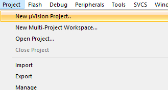
- create a new project naming it as you like and storing it in your preferred folder
Select Device and startup files #
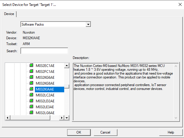
- Select the device you’re using (for NuMaker-M032KI v1.0 it’s M032KIAAE; you’ll find it under “Nuvoton -> NuMicro M0 Family -> M031 -> M032KIAAE”)
- in the “Manage Run-Time Environment” select “Device -> Startup” to directly include the System Startup files for Nuvoton M03x Series (this is part of CMSIS-Core and is needed to get the Controller started correctly when powering up or after reset)
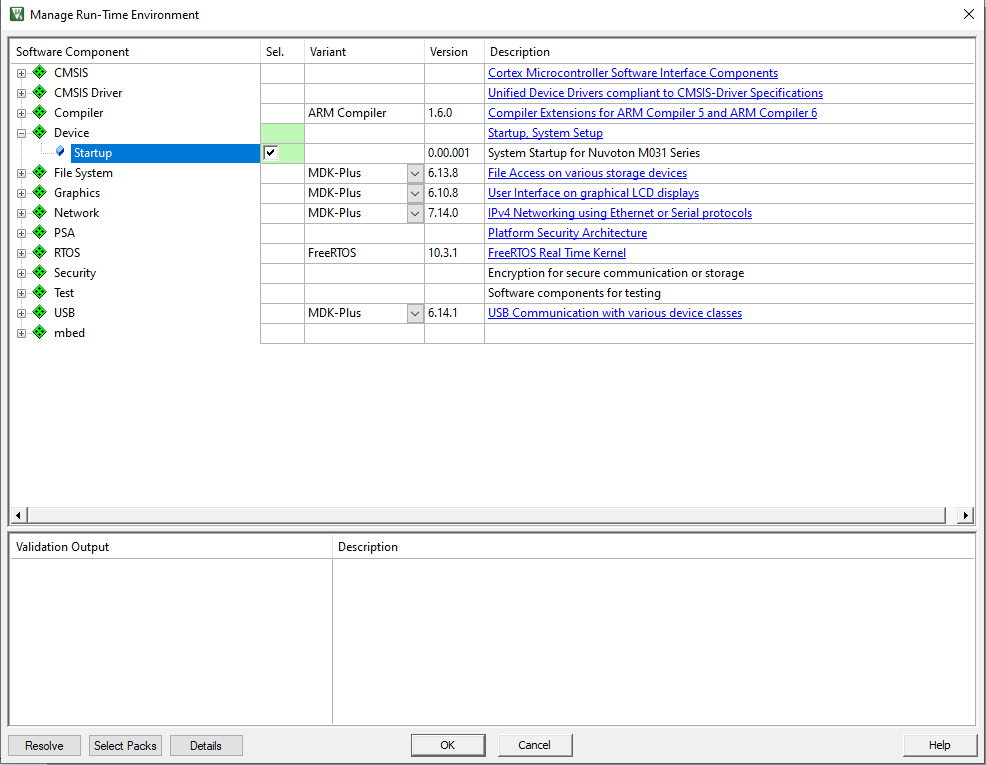
- you can also add the startup files later, but the easiest way is doing it the way described before
- besides your application code these are the minimum needed files to get your controller up and running
You’re now ready to add further files from the BSP and your own application code
Step 2: adding further files and app code to your project #
Adding via project window #
- in the project overview you now see:
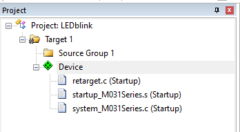
- you can add Groups and existing files (e.g. from BSP) or your own files to the project
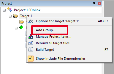
- by right-clicking on a target you can add new Groups
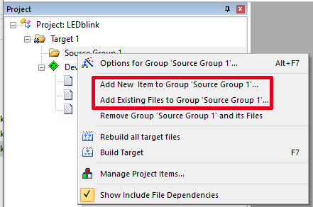
- by right-clicking on the certain groups you can add new files or existing files
- You also have the option to rename your Targets and Groups. Click on a target and then click on it again (no double-clicking) or use F2 on the keyboard
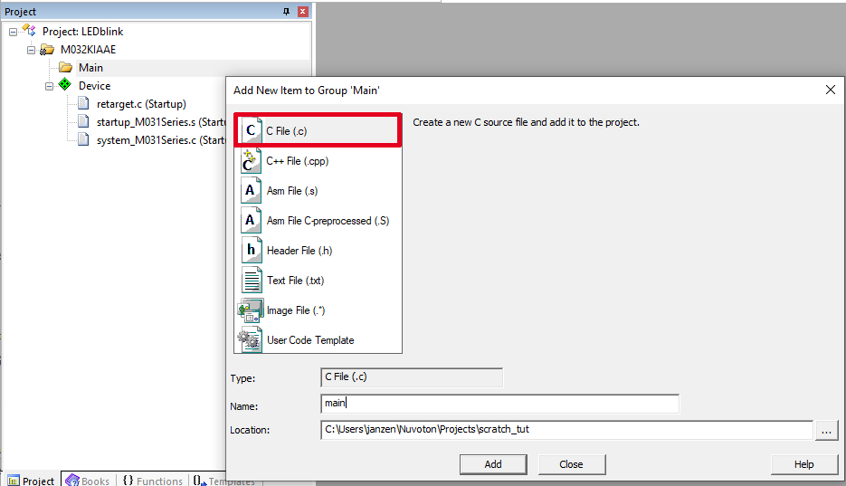
- You can rename “Target 1” to “M032KIAAE”
- Rename “Source Groupe 1” to “Main” (or something else) and add one new c-file (via Add New Item) which will be your main file
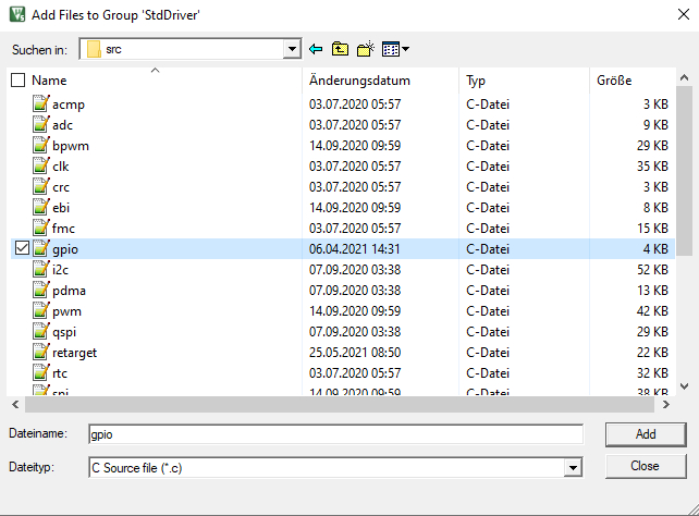
- Add another group to your project, naming it “StdDriver”
- Add an existing file to the StdDriver Group (via right-clicking): navigate to the BSP folder on your PC, then go to “Library -> StdDriver -> src” and add gpio.c
- In the gpio.c and gpio.h there are some helpful definitions of macros and functions for configuring the GPIO Ports
- Using this functions and macros is the easiest way to configure your GPIOs to get the user LED on the board blinking
Adding via “Manage Project Items…” #
- An alternative way for doing above mentioned steps is the “Manage Project Items…” window
- To open it you have several ways
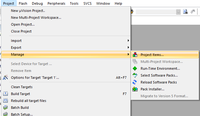
- Go to “Project -> Manage -> Project Items…”
- Use the dedicated icon on the toolbar
- Right click on the target or a group in the project tree and go to “Manage Project items…”
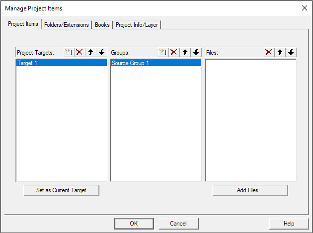
- By double-clicking you can rename targets and groups
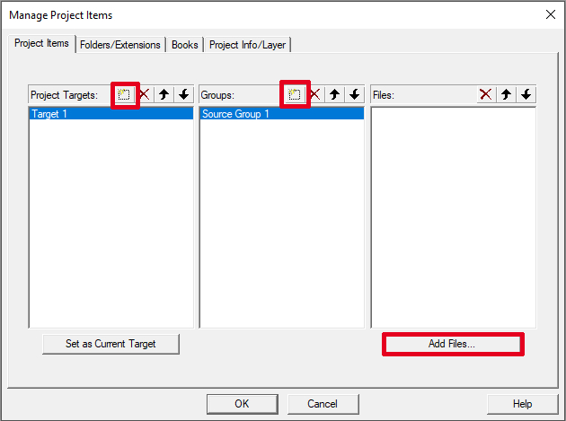
- Further you can add targets, groups and existing files in the dedicated part of this window
Step 3: main file #
Header files #
- Make sure to always include all necessary header files in your main file. For all Nuvoton projects you have to include at least the device specific header file. This is the device specific Peripheral Access Layer Header File, means that all peripheral header files are included here, too.
- So in this case include “M031Series.h”
#include "M031Series.h"Initializations, functions and macros #
- Now you have to make all necessary initializations of your system (additionally to those already done during startup); e.g. set the correct modes for the GPIOs
- As we want to blink the red user LED on the NuMaker-M032KI we have to set the dedicated I/O to Output Mode. The user LED is connected to Port B Pin 14 (PB14)
- You find the needed function for doing this initialization in the gpio.c driver you have added to the project before (void GPIO_SetMode(GPIO_T *port, uint32_t u32PinMask, uint32_t u32Mode))
- Insert following in your main function
GPIO_SetMode(PB, BIT14, GPIO_MODE_OUTPUT);- There are different ways to write working code for blinking the LED, but the easiest one is to use the GPIO_TOGGLE function-like macro you’ll find in the gpio.h
#define GPIO_TOGGLE(u32Pin) ((u32Pin) ^=1) - Use this macro in your main loop for toggling PB14 and let the LED blink
GPIO_TOGGLE(PB14);- Now you need a delay to actually let the LED blink. In the first step you can use a “for loop” for inserting a delay
- Use a value of about 3200000 to get a delay of about one second
for(i=0; i < 3200000; i++)- Don’t forget to insert the necessary variable declaration for “i” into your main function. (You maybe need further declarations in your future projects)
uint32_t i;(sized integer types are defined in the stdint.h which is found under C:\Keil_v5\ARM\ARMCC\include)
Final code #
The whole main code is not more than this:
#include "M031Series.h"

int main(){
      uint32_t i;
      GPIO_SetMode(PB, BIT14, GPIO_MODE_OUTPUT);

      while(1){
             GPIO_TOGGLE(PB14);
             for(i=0; i < 3200000; i++);
             }
}
Step 4: Set correct “Options for Target…” #
Options for Target #
- Before we can build the code and run it on the microcontroller we have to make some settings in the “Options for Target…”
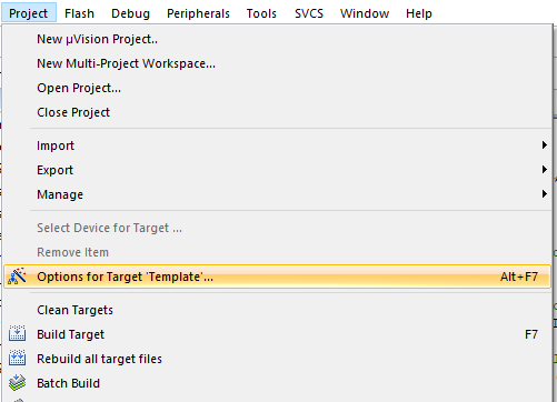
- Open the “Options for Target…” via tab “Project” or via the dedicated icon
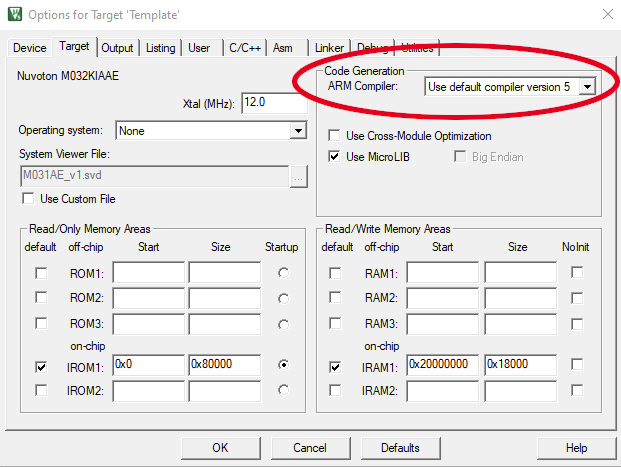
- Under tab “Target” set the ARM Compiler to “Use default compiler version 5” via the dropdown list (this is needed for making all files from the current Nuvoton BSP work together correctly)
- Under tab “C/C++” you have to set all the include paths for the project (so that all necessary header files are included correctly)
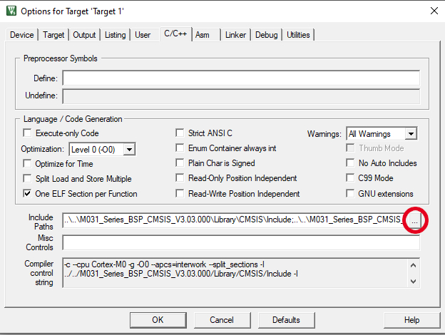
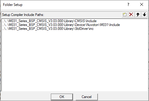
- Set the paths to include CMSIS, Device and StdDriver header files
…\M031_Series_BSP_CMSIS_V3.03.000\Library\CMSIS\Include
..\..\M031_Series_BSP_CMSIS_V3.03.000\Library\Device\Nuvoton\M031\Include
..\..\M031_Series_BSP_CMSIS_V3.03.000\Library\StdDriver\inc
- You maybe need to include some other header files in your future projects. Don’t forget to add the correct paths here.
Connect the board and make further settings #
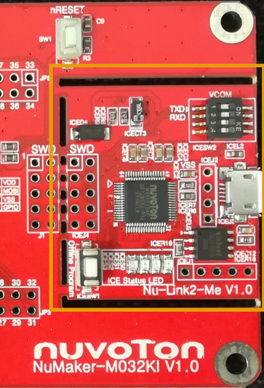
- If you haven’t connected your board via USB to your PC yet, do it now to make the last adjustments before debugging and programming the code on your board. Make sure to use the USB port on the Nu-Link2-Me part of the board
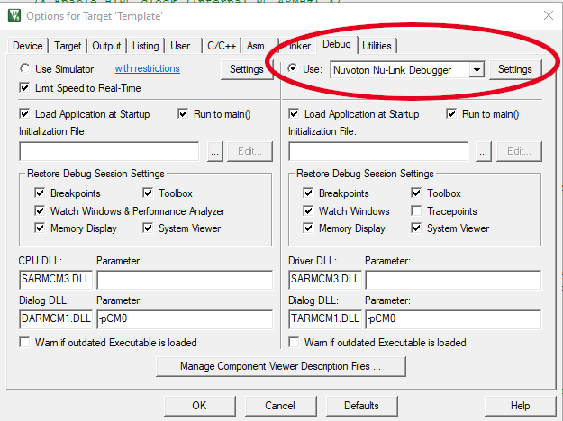
- Go to the “Debug” Tab in the “Options for Target…” and select “Nuvoton Nu-Link Debugger” from the dropdown list to use this as debugger
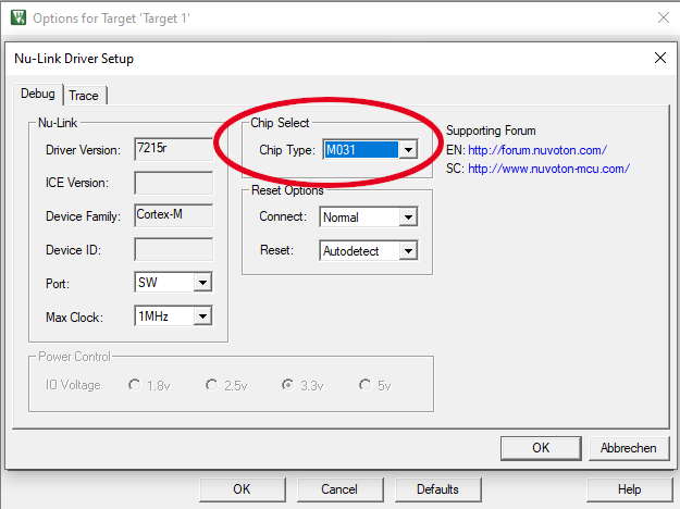
- Open the settings afterwards and set Chip Type to: “M031”
- You should now be able to Build and run the code on your board (or make some debugging before)
Step 5: Building, debugging and running code #
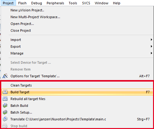
Build Options (or use dedicated icons on the toolbar):
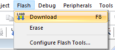
Download (or use dedicated icon on the toolbar):
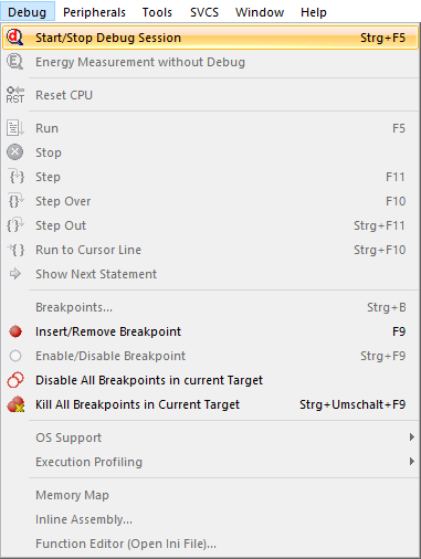
Debug Options (or use dedicated icons on the toolbar):
Conclusion #
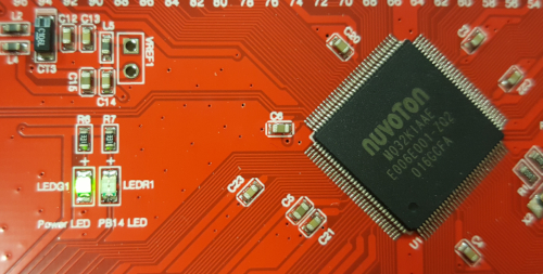
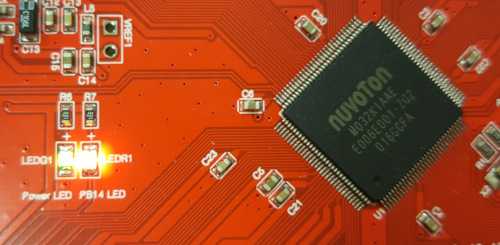
If you’ve set up everything correctly and no errors arose, the red User LED (LEDR1) on your NuMaker Board should blink about every one second.
Now that you’ve gone through the getting started tutorials, make sure to check out also the tutorials on Nuvoton’s NuTool Suite. This tools will help to reduce development efforts and time.


