
In the previous tutorial, we saw how to build and flash ESP-AT, but we didn’t look at what configuration options were available. In this tutorial we will learn how to configure the ESP-AT firmware in order to use the UART-0 interface for both info logging and AT commands.
For this tutorial you’ll need:
- PC running Linux
- The examples shown here are running on Ubuntu 20.04
- Espressif ESP32-DEVKIT-C – Contact us for more info
Introduction #
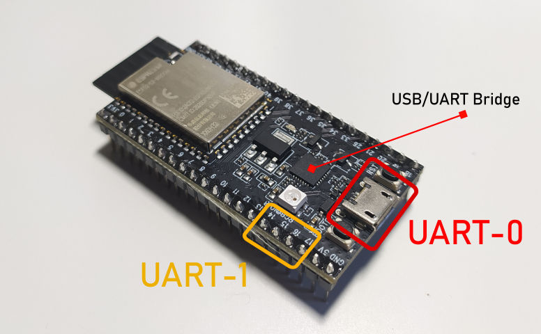
All the ESP* modules come with the default AT firmware installed, but this firmware sends logs to the UART-0 interface (on our board, this is connected to the USB port throught the USB/UART bridge), and expects the commands to be sent to the UART-1 interface:
To use the UART-0 interface for both logs and commands, thus not requiring any additional USB/UART bridge, we must alter the configuration of the ESP-AT firmware. Recompiling the AT firmware is useful for other purposes too, for instance the SPP protocol of classic BT is not enabled by default, and can be enabled with a few configuration changes.
Updating Configuration with menuconfig #
First let’s check to see if the UART-0 interface is set as default console output port, so first head to the location you downloaded the ESP-AT source and open the menuconfig tool:
cd ~/esp-at
./build.py menuconfig
Go to Component config > Common ESP-related and you should see UART for console output set to:
Default: UART0, TX=GPIO1, RX=GPIO3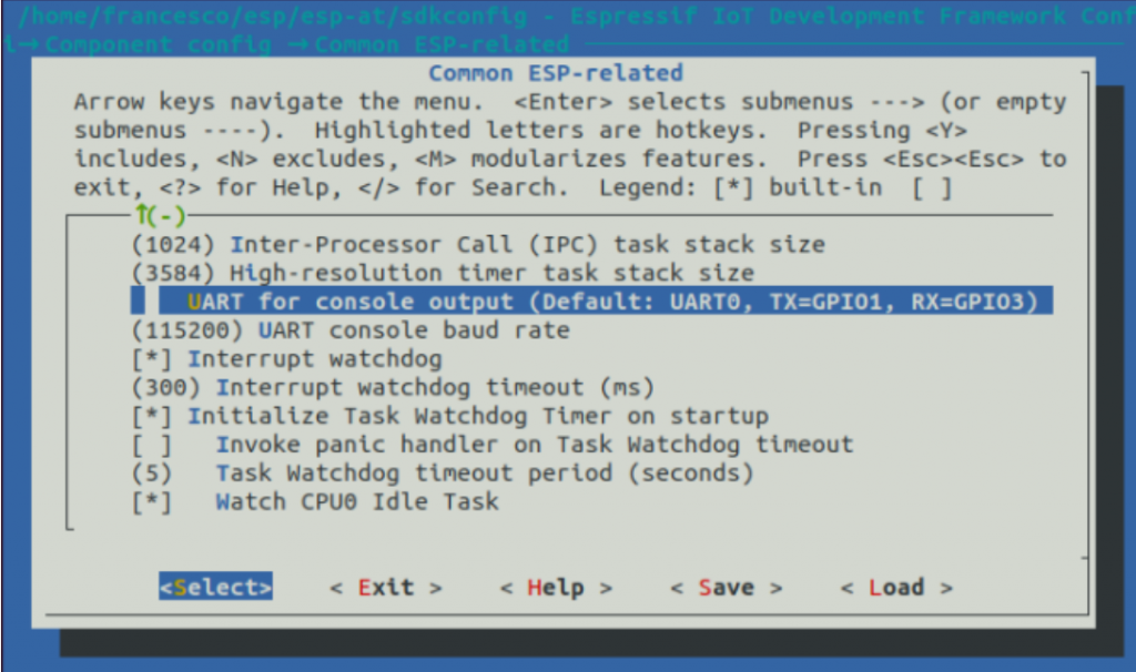
Note that this is the console output port, it is not the command port, the configuration for the command port is not in the menuconfig, but it is in a configuration file:
gedit components/customized_partitions/raw_data/factory_param/factory_param_data.csv &This file lists all the modules and the default GPIOs and parameters for the AT firmware. Since we’re using the ESP32-WROOM-32*, we’ll need to update line 2:
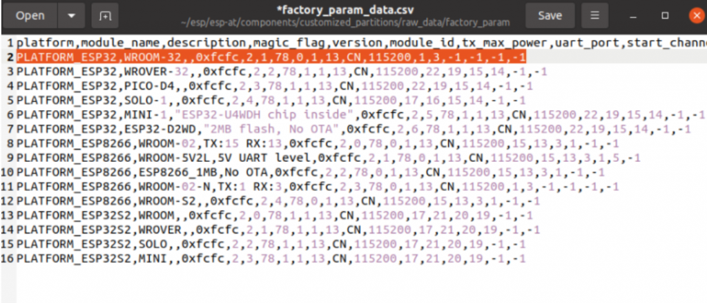
With this row we replace the UART (command) port to UART-0, the TX pin to 1 and RX to 3, these are the GPIOs linked to the USB/UART bridge on the ESP32-DEVKIT-C:
PLATFORM_ESP32,WROOM-32,,0xfcfc,2,1,78,0,1,13,CN,115200,1,3,-1,-1,-1,-1Build & Flash #
We are now ready to build and flash the modified firmware:
./build.py flashAs in the last tutorial, if you get a SerialException:
you’ll need to add the current user to the group dialout and restart the system:
sudo adduser $USER dialout
sudo reboot
AT command test #
To test the firmware we have just flashed, open up a serial terminal – I am going to use GTKTerm, which can be found and installed from the software center.
ESP-AT expects CR LF as new line so we must set Configuration->CR LF auto. Then open Configuration->Port and set the serial port configuration to:
Baud Rate: 115200
Parity: none
Bits: 8
Stopbits: 1
Flow control: none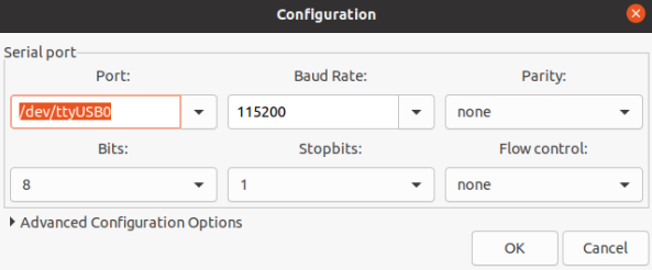
If everything was configured correctly, we should see the log output (since the UART-0 interface is still the log port), and once the module has initialised we should see ready outputted. You can now give the command at, which is a test command, and input the CR LF – this is achieved in GTKTerm by pressing both ENTER and CTRL-J:
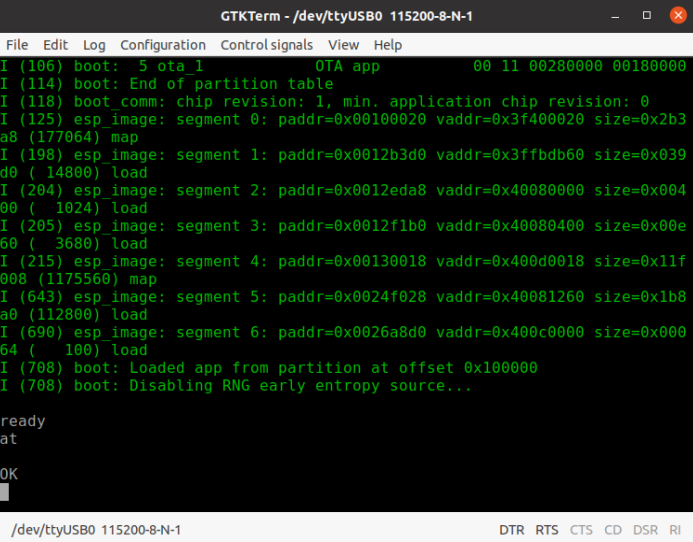
The firmware should reply OK and thus our firmware has been correctly configured.
Conclusion #
We configured and compiled the ESP-AT firmware to change the command output from the default UART-1 interface to the UART-0 interface, which is connected to the usb port in the ESP32-DEVKIT-C and we sent our first command and checked that everything works correctly. We are now ready to use the AT firmware for both WiFi and BLE application.
Next #
- Start with a simple BT SPP example: Bluetooth SPP esp-at


