
- Introduction
- NuTool PinConfigure: making initial pin configuration and generate code
- NuTool ClockConfigure: making initial clock configurations and generate code
- NuTool CodeGenerator: Generate Keil, IAR, GCC Project Templates with initial configuration
- NuTool PinView: visualizing and monitoring of current I/O status
- Conclusion
Introduction #
Nuvoton’s NuTool Suite helps you to make initialization of your Nuvoton MCU very easy and fast, thus reducing development efforts and time.
The NuTool Suite currently consists of six tools:
- NuTool-PinConfigure
- NuTool-ClockConfigure
- NuTool-CodeGenerator (currently only a very limited number of Nuvoton parts are supported; this tool integrates the PinConfigure and ClockConfigure and an additional PeripheralConfigure)
- NuTool-PinView (for monitoring and visualizing the current I/O status)
- NuTool-USB to Serial Port (application software, it passes through or monitor I2C/SPI/CAN data from Nu-Link2-Pro adapter; not introduced here)
- NuConsole for message-logging via SWD. (not introduced here)
You can download the particular tools directly from Nuvoton’s dedicated Website.
You’ll find current User Manuals for more detailed information in the download folders or program folder (after installation) respectively.
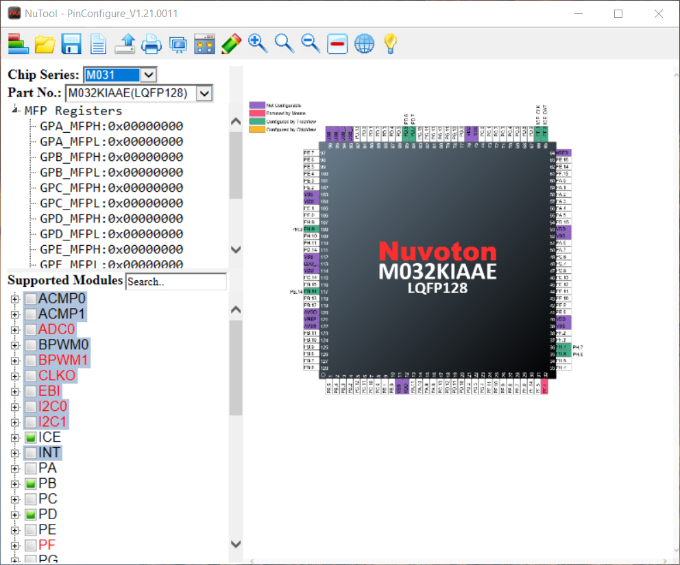
NuTool PinConfigure: making initial pin configuration and generate code #
- Main Window after opening the NuTool PinConfigure
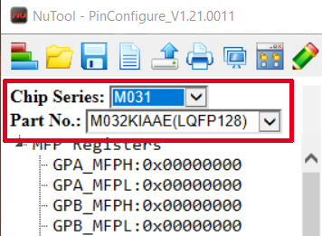
First steps #
- Select “Chip Series” from dropdown list (Note that e.g. M031 Series also includes M032 or M0A21 also includes M0A23)
- Select “Part No.” from dropdown list
There are different ways of configuring pins using the PinConfigure Tool.
- Writing directly to MFP Registers (multi-function port)
- Configure pins via “Module Tree View”
- Configure pins via “Chip View”
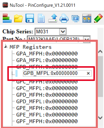
Configuring pins writing directly to MFP Registers #
- By double clicking on the certain register you can directly write to it
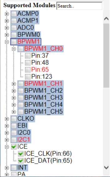
Pin Configuration via “Module Tree View” #
- you can configure different modules and dedicated pins by clicking it in the Module Tree
- Steel blue coloured modules show that there are multiple pin options for one module
- Red coloured modules indicate pin conflicts (if you click on a red coloured pin the tool will show you the conflict and suggest a conflict solution)
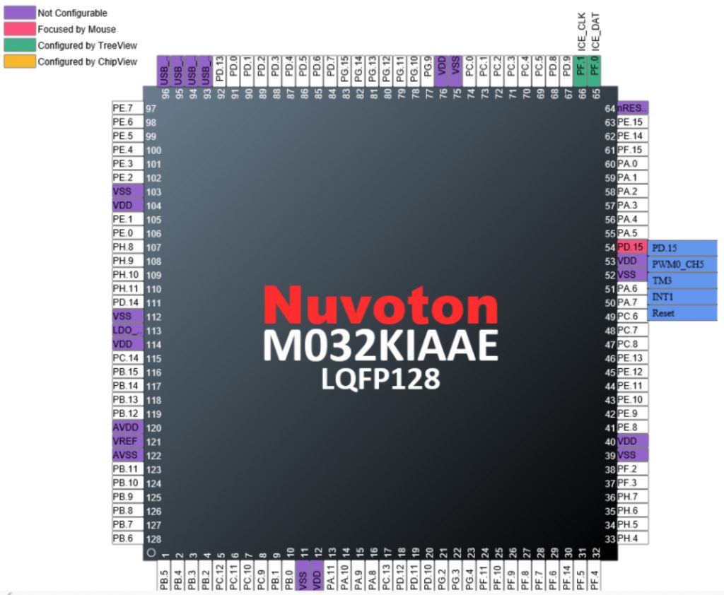
Pin Configuration via Chip View #
- Configure Pins by clicking it in the chip view and selecting the desired function
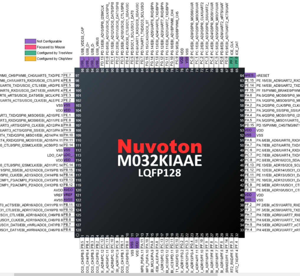
You can also switch pin description to show all the functions of every pin beside the pin:
Generating Code #
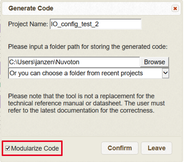
When you’ve finished your pin configuration you can generate the initialization code. You can then add it to your Keil, IAR or NuEclipse project.
When generating the code you have the option to modularize the code. If you click this option you will get a header file and a source file containing dedicated functions for initialization. If you don’t choose this option you will get a single source file with a single sys_init function writing directly to MFP registers. You can easily figure out the differences by yourself making a test config.
Further options of the PinConfigure Tool #
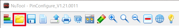
Load Configuration
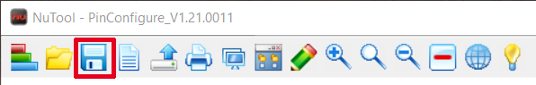
Save Configuration
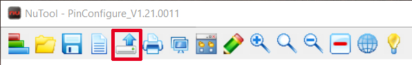
Connect to Target Chip (option for real-time debugging in NuEclipse IDE only)
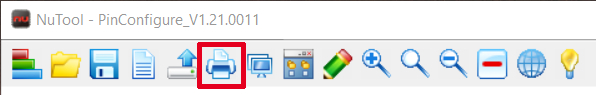
Print Report (of configuration)
Generate Report (of configuration)
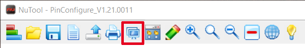
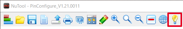
Open User Manual
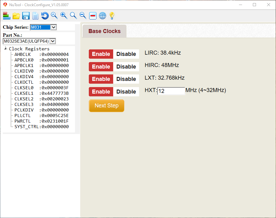
NuTool ClockConfigure: making initial clock configurations and generate code #
- Main Window after opening the NuTool ClockConfigure
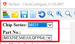
Before starting configuration of the clocks, you have to:
- Select “Chip Series” from dropdown list (Note that e.g. M031 Series also includes M032; current version [V1.05.0007] only supports 32-bit Cortex-M MCUs)
- Select “Part No.” from dropdown list (in current version [V1.05.0007] some parts, e.g. from M032 series are missing; but you can make for example configuration for M032KIAAE, which is missing here, based on the M032SE3AE which has the same clock structure)
Also here you have different possibilities of configuring the clocks in the ClockConfigure Tool.
- Writing directly to Clock Registers
- Configure clocks via “Configuring Wizard”
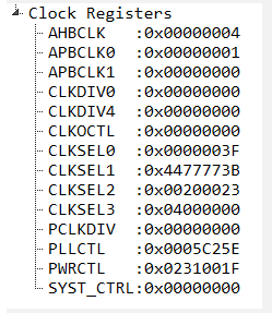
Configuring clocks writing directly to Clock Registers #
- By double clicking on the certain register you can directly write to it and configure the clocks
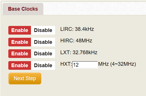
Configuring clocks via “Configuring Wizard” #
Step 1: Enable/Disable Base Clocks
Step 2: Enable/Disable and configure PLL (if available)
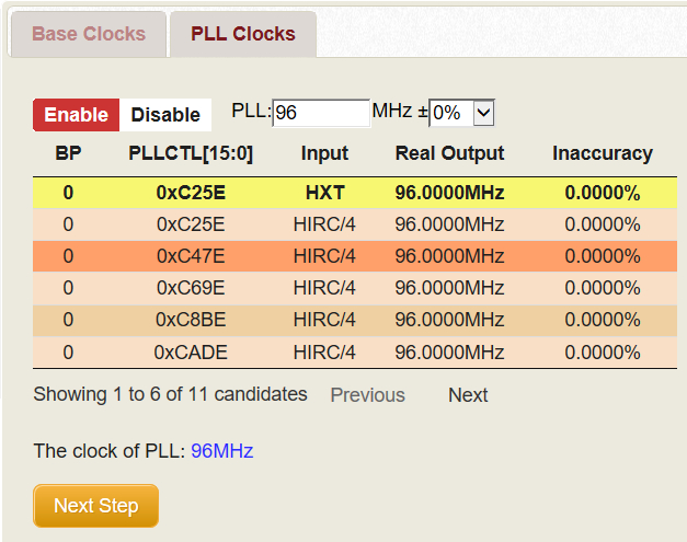
- you can select different Inputs/settings for PLL from the list by clicking on it
Step 3: Configure HCLK/PCLK
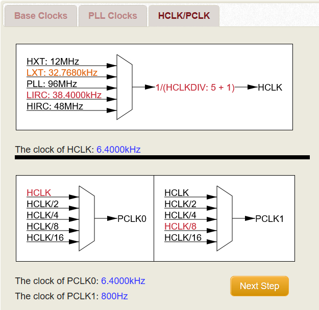
- you can select input (one of the different sources) and divider for HCLK (System Clock)
- then you can select input for PCLK0/1 (Peripherals Clock)
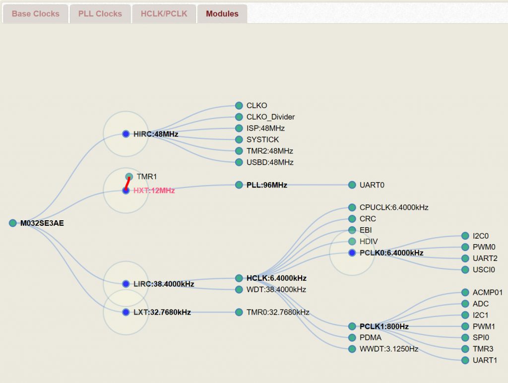
Step 4: Overview of configuration/ making additional configurations
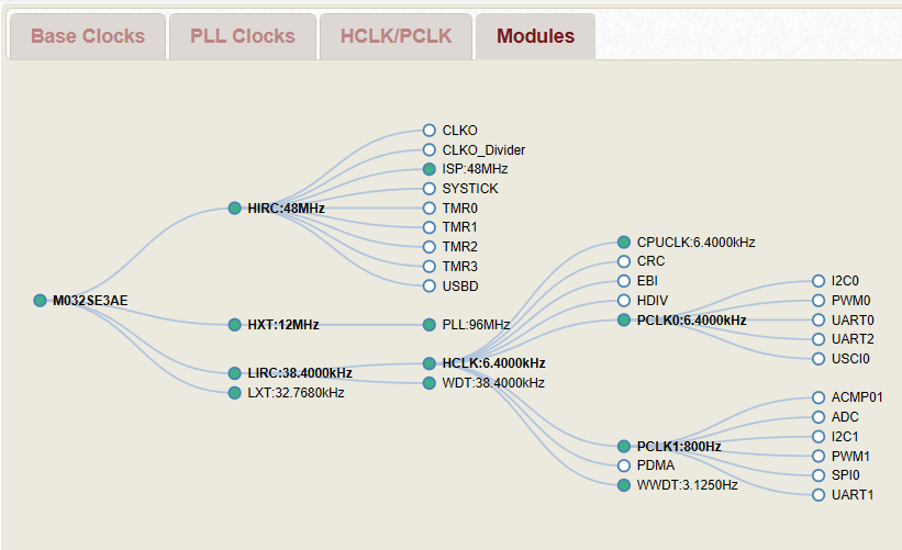
- in this last step you get an complete overview of your current configuration
- here you can also do further configurations
- enable further modules (e.g. one of the timers) by double-clicking it
- connecting modules to an other clock source by drag and drop (if you click on the module you want to drag to another source, you will see the possible source you can connect it to; dot colour will change from green to blue and a circle around the source)
After you’ve done all configurations you’re ready to generate code and use it in your project.
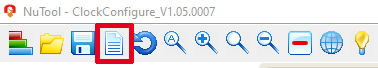
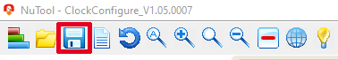
Generating Code #
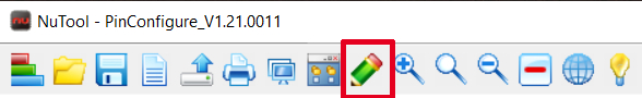
Generate code by clicking on the dedicated icon
Further options of the PinConfigure Tool #
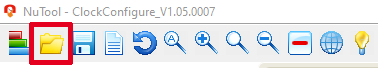
Load configuration
Save configuration
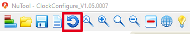
Return to default settings (all configurations will be deleted; you can save current config before)
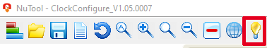
Open User Manual
NuTool CodeGenerator: Generate Keil, IAR, GCC Project Templates with initial configuration #
The NuTool CodeGenerator combines the PinConfigure, ClockConfigure and a PeripheralConfigure Tool. With the Peripheral Configure you can make different settings for each peripheral of the certain MCU. E.g. select PWM function, enable diverse PWM channels, set PWM frequency and duty cycle.
After you have done all the configurations you can generate the code and further write your own application. The CodeGenerator generates project templates for Keil, IAR and GCC including all your configurations.
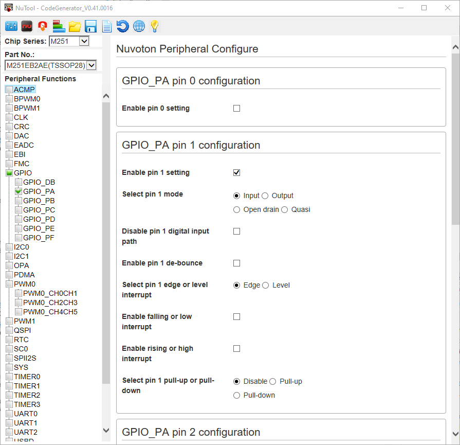
Peripheral Configure #
When you open the NuTool CodeGenerator you get directly to the peripheral configure part:
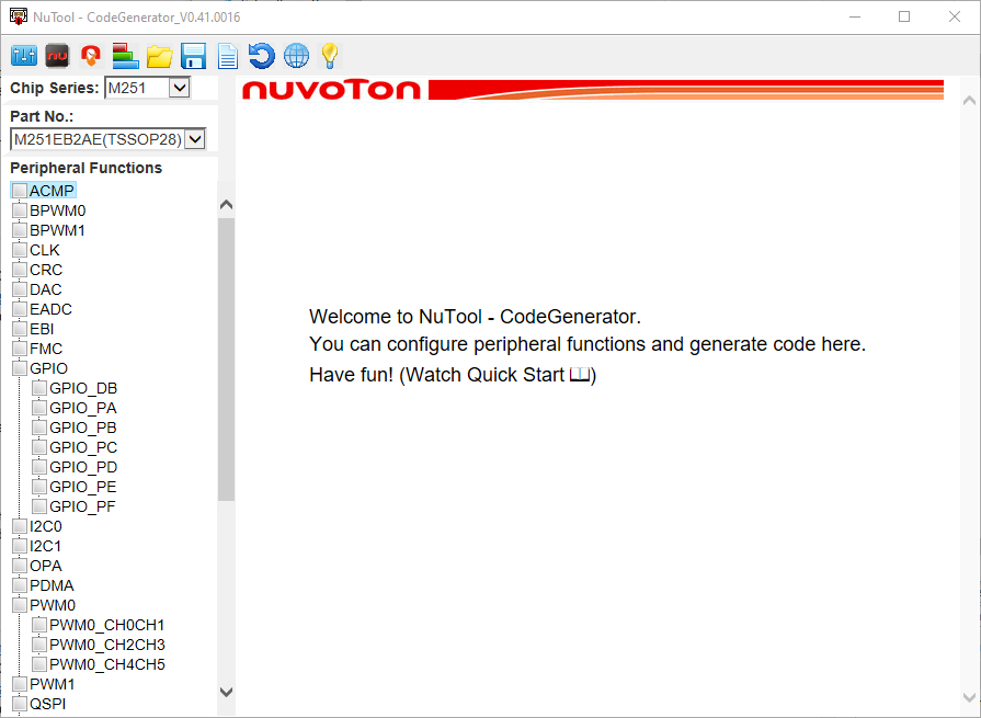
You can choose all peripherals you need for your project. Just check the box and click on each peripheral to configure it
When you’re done making all peripheral configurations you can go on making the pin configurations.
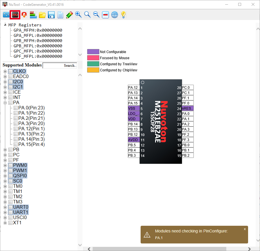
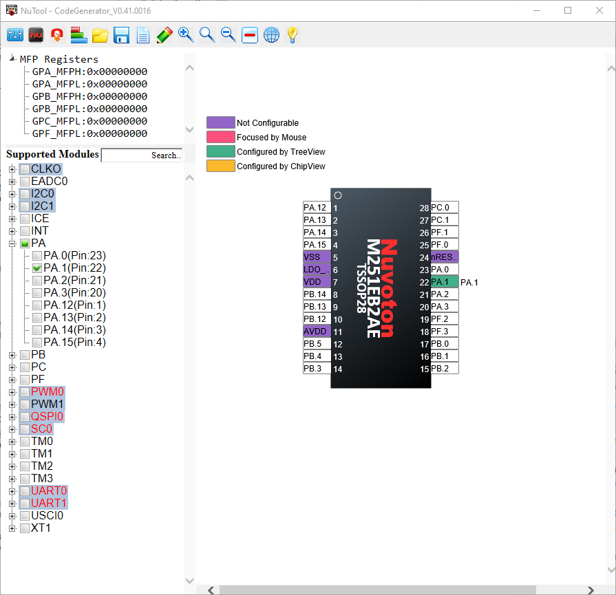
Pin Configure #
The pin configure integrated in the CodeGenerator is the same as the standalone NuTool PinConfigure. The tool is reminding you which peripheral modules you configure before need pin configuration. Just make your configurations and go on with the ClockConfigure.
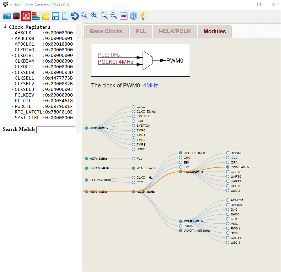
Clock Configure #
The Clock Configure tool integrated here is also the same as the standalone tool found in the NuTool Suite. The ClockConfigure will also remind you which peripheral modules need clock configuration.
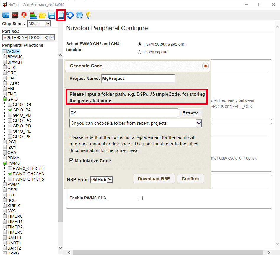
Generating Code #
When all settings are made you can generate the code. You have to store the code in an folder inside the BSP. Most suitable would be the SampleCode folder. You have also the option to modularize the code here. If you haven’t downloaded the BSP before you can use the “Download BSP” button here to download it from either GitHub, GitLab or Gitee.
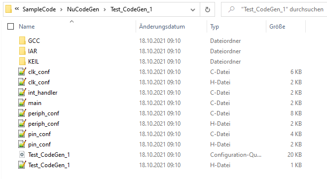
NuTool CodeGenerator will create a new folder inside the BSP SampleCode called “NuCodeGen”. Inside this folder you will find your generated projects.
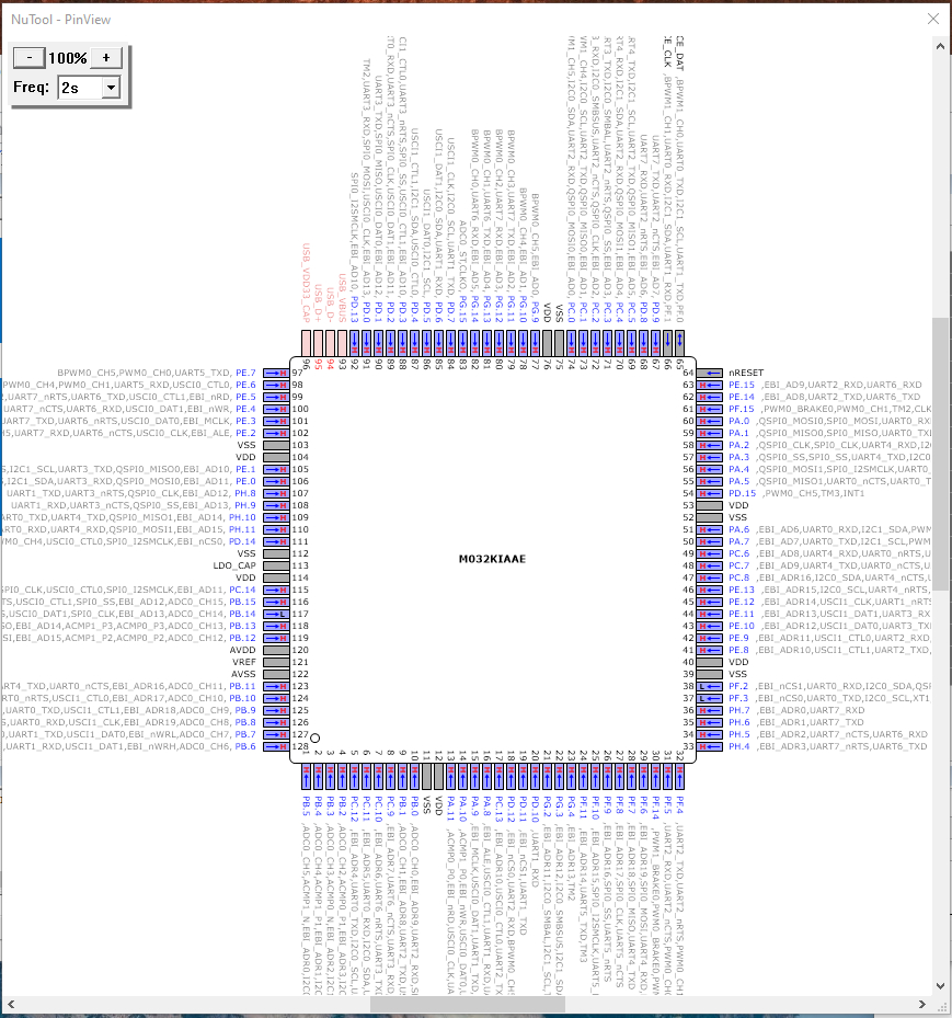
NuTool PinView: visualizing and monitoring of current I/O status #
(please make sure to fulfil all system requirements described in the User Manual when using it with your own boards)
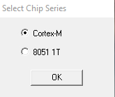
When you open the PinView Tool you first have to select the chip series; either Cortex-M or 8051 1T
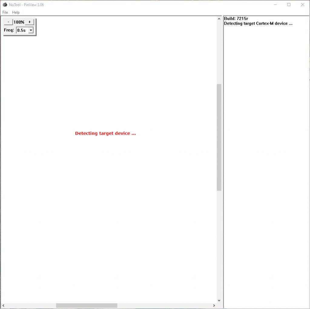
If no target device is connected yet you’ll get following window showing up
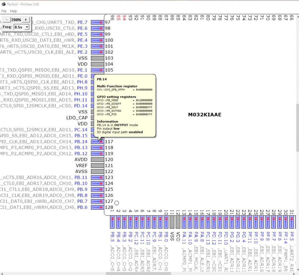
After connecting the device, you get the chip view and the current status of all pins and I/Os.
If you have running the blinking LED project we’ve set up in the other tutorial, you will see PB.14 changing from H to L and from L to H again every second.

If you hover over the respective pin you also see information on the configuration of it
Pin View IDE Plug-in #
The NuTool PinView can also be used as Plug-in for IAR and Keil IDEs. PinView plug-in is included in the Nu-Link Driver for each IDE.
You can open it after you’ve started a debug session in the IDE.
Keil IDE as an Example
- Open Keil IDE
- Open you’re project you want to debug
- Start debug session
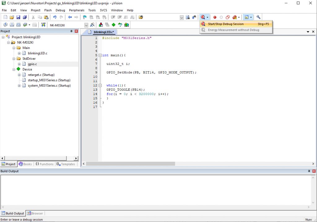
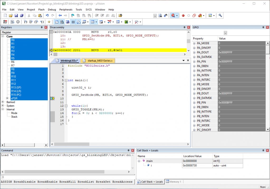
- When debug session is running you can open PinView from the Debug options (clicking on Debug Tab and then selecting NuTool-PinView)
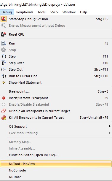
- NuTool-PinView will open directly in Keil
Conclusion #
The NuTool Suite contains some very helpful tools to ease MCU initialization. It’s not more than just clicking the required options and generating code, which then can be added to your project. Or just use the generated project templates.
Check out also our other Nuvoton tutorials. You can try using NuTool Suite when going through our Getting Started with NuMaker-M032KI – Part 2 here


